Cuisinart TOA-60 Manual: A Comprehensive Guide
Welcome! This detailed manual unlocks the full potential of your Cuisinart TOA-60‚ offering a roadmap to exceptional cooking and effortless operation.
Follow these instructions carefully for optimal performance‚ safety‚ and lasting enjoyment of your new kitchen appliance.
Congratulations on acquiring the Cuisinart TOA-60 Toaster Oven Airfryer! This versatile appliance combines the functionality of a full-size oven with the speed and convenience of air frying technology. It’s designed to be a kitchen workhorse‚ capable of handling everything from toasting bread and baking cookies to roasting vegetables and frying chicken – all with exceptional results.
The TOA-60 isn’t just about convenience; it’s about expanding your culinary possibilities. Its spacious interior accommodates a variety of dishes‚ while its intuitive controls make operation straightforward‚ even for novice cooks. This manual serves as your comprehensive guide‚ walking you through every aspect of the appliance‚ from initial setup to mastering its diverse cooking functions.
Prepare to experience a new level of cooking flexibility and enjoy healthier‚ delicious meals with the Cuisinart TOA-60. We’re confident it will quickly become an indispensable part of your kitchen routine.
Unboxing and Initial Setup
Carefully unpack your Cuisinart TOA-60 and ensure all components are present. You should find the toaster oven airfryer itself‚ an air fry basket‚ a baking pan‚ a broiling rack‚ and a wire rack. Also‚ verify the inclusion of this manual and any accompanying recipe booklets.
Before first use‚ remove all packaging materials‚ including any protective films. Wipe down the interior and exterior with a damp cloth. Important: Do not immerse the appliance in water. Place the TOA-60 on a stable‚ heat-resistant surface with adequate ventilation around it.
Perform a test run by setting the oven to 400°F (200°C) and running it empty for 15-20 minutes. This will burn off any manufacturing residue and eliminate any initial odor. Familiarize yourself with the control panel and accessory placement before beginning your first cooking adventure!
Key Features and Benefits
The Cuisinart TOA-60 is a versatile appliance combining seven functions in one: Air Fry‚ Bake‚ Broil‚ Toast‚ Warm‚ and more! Its spacious interior accommodates a 12-inch pizza or 6 slices of toast‚ making it ideal for families or meal prepping.
Enjoy healthier cooking with the Air Fry function‚ using little to no oil for crispy‚ delicious results. The adjustable temperature control (80-450°F) and 60-minute timer provide precise cooking control. Benefit from convenient preset functions for popular dishes like fries‚ chicken‚ and bagels.
Cleanup is a breeze thanks to the non-stick interior and dishwasher-safe accessories. The sleek stainless steel design complements any kitchen décor. Experience the convenience and versatility of the TOA-60 – your all-in-one cooking solution!

Understanding the Control Panel
Navigating the controls is simple! The intuitive design features dedicated buttons for functions‚ precise temperature and time adjustments‚ and convenient presets.
Power and Function Buttons
The Power button initiates all operations‚ illuminating the control panel for easy visibility. Adjacent to it‚ you’ll find dedicated function buttons – Air Fry‚ Bake‚ Broil‚ Toast‚ and Warm – each clearly labeled for straightforward selection.
Pressing a function button automatically activates the corresponding cooking mode. A lit indicator confirms your choice. The Start/Pause button then commences the cooking process‚ or allows for mid-cycle adjustments.
A Cancel button immediately halts operation‚ returning the unit to standby mode. These buttons are designed for responsive control‚ ensuring a seamless and intuitive cooking experience. Familiarizing yourself with their placement and function will greatly enhance your efficiency when using the Cuisinart TOA-60. Remember to always ensure the unit is properly set up before initiating any function.
Temperature and Time Controls
Precise temperature control is achieved via the dedicated temperature buttons‚ allowing adjustments from 80°F to 450°F in incremental steps. The current temperature is clearly displayed on the digital screen‚ ensuring accurate cooking. Similarly‚ time adjustments are managed using the hour and minute buttons‚ offering a cooking duration range up to 60 minutes.
For shorter cooking times‚ a timer function allows for precise settings in single-minute increments. The remaining cooking time is continuously displayed‚ providing real-time monitoring. These controls work in tandem to deliver consistent and reliable results.
Experimenting with temperature and time is encouraged to perfect your favorite recipes. Always refer to recipe guidelines as a starting point‚ and adjust as needed to suit your preferences and the specific food being prepared.
Preset Cooking Functions
The Cuisinart TOA-60 boasts several convenient preset functions designed to simplify your cooking experience. These include dedicated settings for French Fries‚ Pizza‚ Chicken‚ Roast‚ and Bake. Each preset automatically optimizes both temperature and time for optimal results with those specific foods.
Selecting a preset is as simple as pressing the corresponding button on the control panel. The oven will then automatically begin the cooking process‚ eliminating the need for manual adjustments. However‚ customization is still possible – you can adjust the time or temperature even when using a preset function.
These presets serve as excellent starting points‚ particularly for novice users. They provide a reliable foundation for achieving delicious and perfectly cooked meals with minimal effort. Explore each preset to discover its capabilities and unlock a world of culinary possibilities.
Using the Cuisinart TOA-60: Cooking Modes
Explore versatile cooking! The TOA-60 offers Air Fry‚ Bake‚ Broil‚ Toast‚ and Warm modes‚ providing flexibility for diverse recipes and culinary creations.
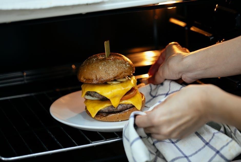
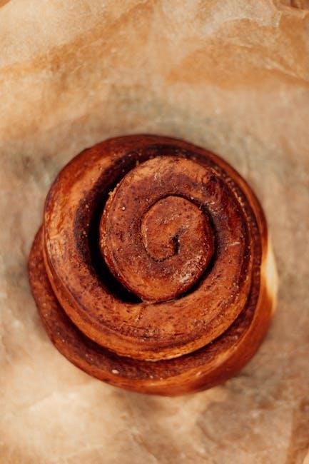
Air Fry Mode: Achieving Crispy Results
Unlock crispy perfection! The Air Fry mode on your Cuisinart TOA-60 utilizes rapid air circulation to cook food with little to no oil‚ delivering deliciously crispy results. This is ideal for favorites like french fries‚ chicken wings‚ and vegetables.
To begin‚ place your food in the included air fry basket‚ ensuring it’s not overcrowded for optimal air flow. Select the “Air Fry” function on the control panel and set your desired temperature – typically between 350°F and 400°F – and cooking time.
For best results‚ consider flipping or shaking the basket halfway through the cooking process to ensure even crisping. Experiment with different temperatures and times to find what works best for your preferred level of crispiness. Remember‚ preheating the toaster oven for a few minutes can also enhance the final outcome. Enjoy guilt-free‚ crispy goodness!
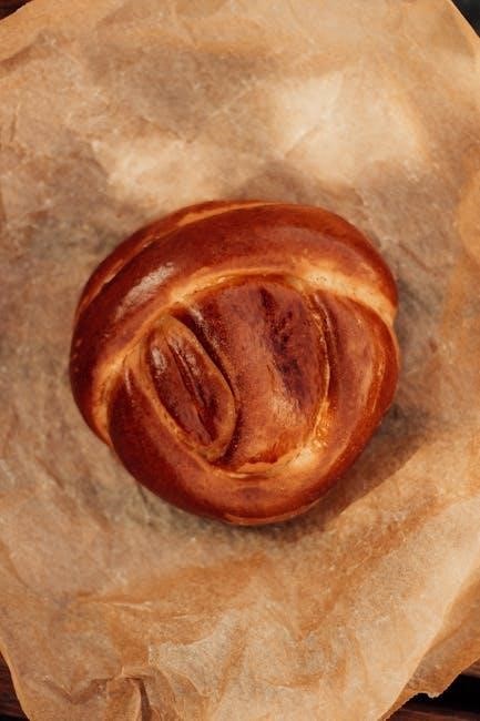
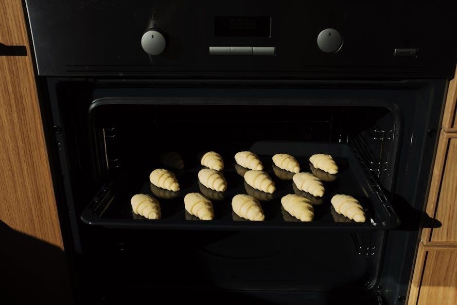
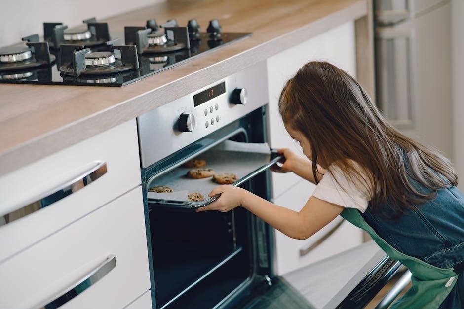
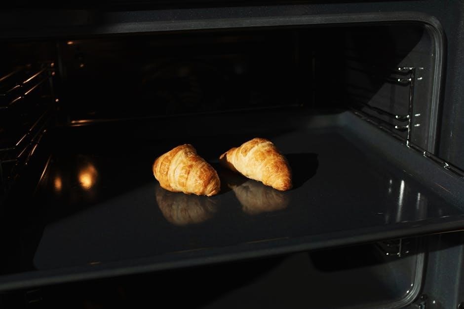
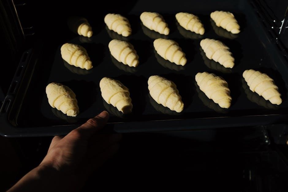
Bake Mode: Traditional Oven Functionality
Experience conventional baking! The Bake mode on your Cuisinart TOA-60 replicates the functionality of a traditional oven‚ allowing you to bake a wide variety of dishes. This is perfect for cookies‚ cakes‚ casseroles‚ and even small roasts.
Place your food in the included baking pan or on a suitable oven-safe dish. Select the “Bake” function on the control panel and set your desired temperature – typically ranging from 250°F to 450°F – and cooking time.
For even baking‚ position the baking pan in the center of the oven. Monitor the cooking process and adjust the time as needed. Using the wire rack can help with air circulation for certain recipes. Remember to always check for doneness using a food thermometer to ensure food safety and optimal results.
Broil Mode: For Quick Browning and Grilling
Achieve a beautiful‚ browned finish! The Broil mode on your Cuisinart TOA-60 delivers intense‚ direct heat from above‚ ideal for quick browning‚ grilling‚ and finishing dishes. It’s fantastic for melting cheese on open-faced sandwiches‚ browning the tops of casseroles‚ or grilling chicken and fish.
Always use the broiling rack when utilizing this function‚ positioning it closer to the heating element for optimal results. Select “Broil” on the control panel. Preheating is generally not required‚ but can enhance browning.
Monitor your food very closely‚ as broiling happens quickly! Flip food halfway through for even cooking. For safety‚ leave the oven door slightly ajar during broiling. Remember to adjust cooking times based on food thickness and desired level of doneness.
Toast Mode: Perfect Toast Every Time
Enjoy consistently golden-brown toast! The Cuisinart TOA-60’s Toast mode is designed to deliver perfectly toasted bread‚ bagels‚ and pastries with ease. Simply insert your bread slices‚ select the desired darkness level using the shade control dial – ranging from light to dark – and press the “Toast” button.
For bagels‚ utilize the dedicated “Bagel” setting for optimal toasting‚ which toasts the cut side more intensely. The TOA-60 automatically adjusts the toasting time based on your selected shade.
Monitor the toasting process; you can always press the “Cancel” button to stop it mid-cycle. Remember that different bread types may require slight adjustments to the shade setting for your preferred level of toastiness.
Warm Mode: Keeping Food at Serving Temperature
Maintain ideal serving temperatures! The Cuisinart TOA-60’s Warm mode is perfect for holding cooked food at a safe and enjoyable temperature until you’re ready to serve. This function prevents food from getting cold while you finish preparing the rest of your meal.
To activate Warm mode‚ simply press the “Warm” button. The oven will operate at a low‚ consistent temperature‚ typically around 170°F (77°C). It’s ideal for keeping cooked meats‚ vegetables‚ or baked goods warm for extended periods.
Avoid using Warm mode for prolonged storage‚ as it’s designed for short-term temperature maintenance. Regularly check the food to ensure it remains at a palatable temperature and hasn’t dried out.

Accessories and Their Uses
Unlock versatility! Your Cuisinart TOA-60 includes essential accessories designed to expand your cooking possibilities and enhance your culinary experience significantly.
Air Fry Basket: Maximizing Air Circulation
The Air Fry Basket is crucial for achieving the signature crispy results the Cuisinart TOA-60 is known for. Its design isn’t just about holding your food; it’s engineered to promote optimal air circulation around the food‚ ensuring even cooking and that desirable golden-brown finish.
The basket’s perforated surface allows hot air to reach all sides of your ingredients‚ mimicking the effect of deep frying but with significantly less oil. This leads to healthier‚ yet equally delicious‚ meals. When using the Air Fry Basket‚ avoid overcrowding – food should be arranged in a single layer whenever possible.
Overcrowding restricts airflow and can result in unevenly cooked‚ soggy food; For best results‚ consider cooking in batches. Remember to periodically shake or flip the food during the air frying process to guarantee consistent crispness. The basket is also designed for easy cleaning‚ often being dishwasher safe – check the cleaning instructions for confirmation.
Baking Pan: For Cakes‚ Cookies‚ and More
The included Baking Pan expands the Cuisinart TOA-60’s versatility beyond air frying‚ allowing you to create a wide array of baked goods. From decadent cakes and chewy cookies to savory casseroles and roasted vegetables‚ this pan is a kitchen essential.
Its non-stick coating ensures easy food release and simplifies cleanup. When baking‚ always preheat the toaster oven to the specified temperature before placing the pan inside. Using parchment paper can further prevent sticking and make removal even easier.
Be mindful of the pan’s capacity; avoid overfilling to prevent spills. For even baking‚ position the pan in the center of the oven. The baking pan is typically dishwasher safe‚ but hand washing is recommended to preserve the non-stick coating’s integrity and extend its lifespan.
Broiling Rack: Elevating Food for Even Cooking
The Broiling Rack is specifically designed to work with the TOA-60’s broil function‚ ensuring food is cooked to perfection with a beautifully browned exterior. Elevating your food allows for optimal heat circulation‚ preventing burning and promoting even cooking.
When broiling‚ always position the rack in the upper level of the oven for closer proximity to the heating element. Monitor your food closely during broiling‚ as it cooks rapidly. The rack’s construction allows for easy placement and removal‚ even when handling hot items (oven mitts are essential!).
It’s ideal for broiling meats‚ fish‚ and vegetables. Cleaning the broiling rack is straightforward; it’s typically dishwasher safe‚ but stubborn residue may require a soak in warm‚ soapy water. Regular cleaning prevents buildup and maintains optimal performance.
Wire Rack: Versatile for Various Cooking Needs
The Wire Rack is a remarkably versatile accessory included with your Cuisinart TOA-60. Its open grid design promotes excellent air circulation‚ making it perfect for a wide range of cooking applications beyond just air frying.
Use it for roasting vegetables‚ baking cookies‚ or even reheating leftovers – the rack ensures even heat distribution and crispy results. It’s also excellent for dehydrating foods‚ allowing air to flow around all surfaces. When using the bake function‚ the wire rack prevents food from sticking to the baking pan.
Cleaning is a breeze; the wire rack is typically dishwasher safe. For tougher messes‚ a scrub with warm‚ soapy water will do the trick. Its durable construction ensures long-lasting performance‚ making it an indispensable part of your TOA-60 toolkit.

Cleaning and Maintenance
Preserve performance! Regular cleaning ensures longevity and optimal function of your Cuisinart TOA-60. Follow these simple steps for a spotless appliance.
Cleaning the Interior and Exterior
Maintaining a pristine Cuisinart TOA-60 is crucial for both hygiene and performance. Always ensure the unit is completely cool and unplugged before commencing any cleaning procedures. For the interior‚ remove the crumb tray and wipe it clean after each use to prevent buildup. The interior walls can be wiped down with a damp‚ soapy cloth; avoid abrasive cleaners as they may damage the non-stick coating.
For stubborn food splatters‚ a paste of baking soda and water can be gently applied and left for a few minutes before wiping clean. Rinse thoroughly with a damp cloth and dry completely. The exterior surfaces should be cleaned with a soft‚ damp cloth. Avoid using harsh chemicals or scouring pads‚ as these can scratch the finish. Pay particular attention to the control panel‚ ensuring no moisture enters the buttons or display.
Regular cleaning prevents odors and ensures your TOA-60 continues to deliver delicious results. Remember to dry all components thoroughly before reassembling and using the appliance.
Dishwasher Safe Parts
For convenient cleaning‚ several components of your Cuisinart TOA-60 are dishwasher safe. Specifically‚ the air fry basket‚ baking pan‚ and broiling rack can be safely washed on the top rack of your dishwasher. However‚ it’s always recommended to check your dishwasher’s manual to ensure compatibility with coated cookware.
While dishwasher safe‚ hand washing these parts with warm‚ soapy water can help prolong their lifespan and maintain their non-stick coating. Avoid using harsh detergents or abrasive scrubbers‚ even when hand washing. The wire rack is also dishwasher safe‚ but its delicate construction may benefit from gentle hand washing.
The toaster oven itself‚ including the interior and heating elements‚ should never be immersed in water or placed in the dishwasher. Always ensure all parts are thoroughly dried before reassembling and using the appliance.
Troubleshooting Common Issues
If your Cuisinart TOA-60 isn’t heating‚ first ensure it’s properly plugged in and the outlet is functioning. Check if the timer is set correctly‚ as the unit won’t operate without a set time. For uneven cooking‚ avoid overcrowding the basket or pan‚ and rotate food halfway through the cooking process.
If food is sticking‚ ensure you’re using a light coating of oil when air frying. A thorough cleaning of the air fry basket and baking pan can also resolve this. Smoke during operation may indicate excessive oil or food particles; reduce oil usage and clean the unit.
If the unit shuts off prematurely‚ it may be due to the overheat protection feature. Allow it to cool completely before restarting. If problems persist‚ consult the full manual or contact Cuisinart customer support for assistance.

Safety Precautions
Prioritize safety! Always unplug the TOA-60 before cleaning. Never immerse the appliance in water‚ and keep the cord away from hot surfaces during operation.
Important Safety Instructions
Read carefully before use! To prevent electrical shock‚ never operate the Cuisinart TOA-60 with a damaged cord or plug. Avoid using extension cords. Ensure the appliance is properly grounded.
Hot Surfaces: The TOA-60 gets extremely hot during operation. Always use oven mitts or pot holders when handling hot components‚ like the baking pan or air fry basket; Never touch the interior surfaces while the oven is on or immediately after use.
Proper Ventilation: Ensure adequate air space around the appliance during operation. Do not block the air vents. Avoid placing the TOA-60 under cabinets.
Supervision Required: Close supervision is necessary when the appliance is used by or near children. Never leave the TOA-60 unattended while in operation.
Indoor Use Only: This appliance is intended for indoor household use only. Do not use outdoors.
Electrical Safety Guidelines
Grounding is Essential: The Cuisinart TOA-60 must be grounded to prevent electrical shock. Do not modify the plug. If a grounding type plug is not available‚ consult a qualified electrician.
Voltage Compatibility: Ensure your outlet voltage matches the appliance’s specified voltage (typically 120V). Using an incorrect voltage can cause damage or fire.
Avoid Water Exposure: Never immerse the appliance‚ cord‚ or plug in water or other liquids. If the appliance falls into water‚ unplug it immediately and do not attempt to retrieve it.
Damaged Cord: Regularly inspect the power cord for damage. If the cord is damaged‚ it must be replaced by the manufacturer‚ its service agent‚ or a similarly qualified person.
Unplug When Not In Use: Always unplug the TOA-60 from the outlet when not in use and before cleaning. This prevents accidental operation and ensures safety.
Preventing Overheating and Damage
Proper Ventilation: Ensure adequate airflow around the TOA-60 during operation. Do not block the vents‚ as this can cause overheating and damage the unit. Maintain clearance on all sides.
Avoid Placing on Unstable Surfaces: Position the toaster oven on a stable‚ heat-resistant surface. Uneven surfaces can lead to instability and potential accidents.
Do Not Cover: Never cover the appliance while it’s operating. Covering restricts airflow and can cause overheating‚ potentially leading to a fire hazard.
Cooling Period: Allow the TOA-60 to cool completely before storing. Storing a hot appliance can damage surrounding materials and pose a fire risk.
Use Appropriate Cookware: Only use cookware specifically designed for toaster ovens and air fryers. Avoid metal foil or plastic containers that could melt or cause sparks.